Steer-By-Wire is an interesting technique but its market introduction is slow. In automotive applications, the fail-operational criteria and the targeted safety integrity level imply high complexity and thus high hardware and development costs. The targeted safety integrity levels are lower for mobile machinery but standardised requirements in this area are still under development and the solutions are often highly application-dependent. This report describes a modular and safe solution designed for heavy handling vehicles and used in particular in the international TaxiBot Project.
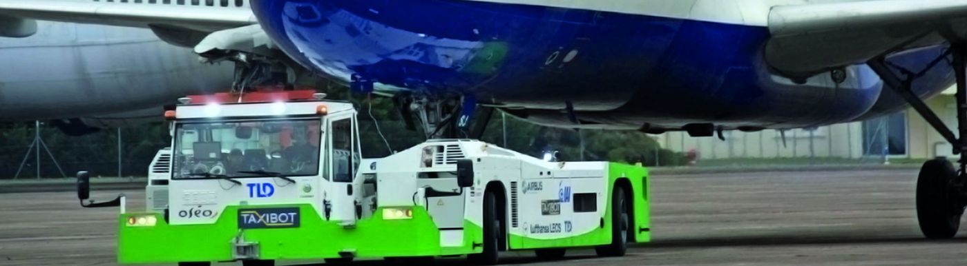
TaxiBot: a new concept of towbarless tractor
At an Airport, Ground Support Equipment (GSE) is found usually on the ramp, the servicing area by the terminal. As its name implies, GSE is there to support the operations of aircraft on the ground. The functions that this equipment plays generally involve ground power operations, aircraft mobility, and loading operations (for both cargo and passengers).
Pushback tugs are mostly used on the ramp to push an aircraft away from the gate when it is ready to leave. These tugs are very powerful and because of the large engines, are sometimes referred to as an engine with wheels. Pushback tugs can also be used to pull aircraft in various situations, such as to a hangar. Some tugs use a tow-bar as a connection between the tug and the aircraft, while other tugs lift the nose gear off the ground to make it easier to tow or push, allowing the tug to manoeuvre the aircraft. This allows more secure control of the aircraft, allowing greater speeds, and lets aircraft be moved without anyone in the cockpit.
But nowadays airplanes still burn a lot of jet fuel using engines while taxiing between terminals and runways, adding to polluting emissions and costing airlines money in fuel and maintenance. Airlines are projected to spend almost $7 billion on fuel just for taxiing in 2020. Then add in foreign object damages on the ground, push back operations and projected carbon emission taxes and the total cost may approach $8.7 billion. Just for taxiing operations.
The main goal of TaxiBot (Taxiing Robot); a, innovative towbarless semi-autonomous tractor developed by IAI with Airbus and TLD, is to significantly reduce fuel burn. That’s why TaxiBot is a tractor that tows the aircraft with its jet engine off from the gate to the runway, at 23 knots, same as current airplane taxi speed. After a normal push back of the aircraft controlled by the tractor driver, the command is transferred to the aircraft pilot, who, with an innovative “Pilot-in- Control” concept, manoeuvers the tractor from the cockpit through a transparent system with the aircraft’s normal steering and braking control devices, just as he would if the aircraft was moving with its own engine power. To reach this target, the aircraft’s nose wheel connects to a rotary turret on the tractor. Thanks to this rotating turret and force control system, very low loads are applied to the nose landing gear. Braking is achieved by the aircraft itself with all kinetic energy being absorbed by the airplane braking system, and not by the tractor, which simply adjusts its speed.
Powered by two hybrid diesel-electricengines, TaxiBot reduces the amount of fuel used in taxi operations by 85 per cent. With TaxiBot in operation in all busy airports, this $8.4 billion expense would drop to $2.9 billion, generating a $5.5 billion annual savings plus cutting CO2 emissions by 20 million tons.
High derived requirements for the steer by wire system
For this innovative vehicle, the expectations of the French vehicle manufacturer TLD for the supplier of the complete steer by wire (SbW) system where very high regarding to the wheel positioning dynamic, accuracy, safety and availability. DINTEC, well-known for its safety-related steering solutions for municipal vehicles, firefighting trucks, sweepers, agricultural machines, was chosen for this demanding project. DINTEC is based in Nantes (France) and is a system supplier for mobile working machines with engineering, prototyping, test and assembling capabilities. Main focus is made on hydraulic, hybrid and electric power packs, power transmission, electro-hydraulic systems, complete electronic architectures including harnesses with a factory a Spain.
Safety and reliability challenges
In pilot controlled mode, the angle requests for all wheels come from the pilot via the IAI controller, smart gateway to the airplane cockpit. The targeted safety integrity level for the low level steering system is SIL2. It sounds first as a common requirement nowadays but each wheel module rotation is mechanically independent and could jeopardize the safety of the vehicle if only one wheel is blocked in rotation. To summarize this requirement in other (probabilistic) words, it is the sum of the probability of dangerous failure of all wheel modules that has to be smaller than 1E-6. Furthermore, the system architecture has to be highly distributedto enable that a single dangerous failure at any electronic control unit does not create a dangerous situation at vehicle level by blocking two wheel modules simultaneously. As a consequence it is imperative to use single components with excellent PFHd and detailed FMEDA.
In driver controlled mode, the angle requests come directly from the driver steering wheel. The expected system safety integrity level is also SIL2 and the set point generation has to be fail-operational. That’s the case for the DINTEC set point generator.
Moreover, due to the relative high vehicle speed during taxiing, the FTT (failure tolerance time), time allowed to detect and to react to every critical failure in the system is low. This fast diagnostic capability of the complete control loop is a tough requirement especially for an electro-hydraulic application on a mobile working machine working in winter and in summer and thus with a high discrepancy in oil viscosity. That’s why DINTEC always use actuators with position feedback sensors, which enables a fast validation of intention.
Performance challenges
First based on complete vehicle simulations from IAI, the steering performance requirements were very high for dynamic performance (pure delay and total response time) and regarding accuracy especially for straight driving in pilot controlled mode.
To reach these dynamic requirements, the main software control loop is running cyclically at 10 ms and both central safety CAN busses at 500 kbits/s. To combine small cyclic transmission intervals and the distributed architecture (an ECU per wheel module) and the redundancies needed for safety a proprietary protocol was used instead of the bandwidth-intensive CANopen Safety (see below ECUS from STW).
To reach these requirements and avoid the use of an expensive and sensitive servo-valves, DINTEC use a symmetrical redundant well-tried electro-hydraulic proportional actuator with LVDT sensor for each spool and a cross monitoring based on these positions feedbacks.
To reach the accuracy requirements, the regulation has to be precise without oscillation and the variable losses of hydraulic motors compensated by software. Sensor calibration and length of hydraulic hoses were also taken deeply in consideration with the vehicle manufacturer.
Challenges met with STW hardware and software products
To achieve the numerous challenges DINTEC worked with off-the-shelf 32 bits controllers from the German company STW based in Kaufbeuren. STW is an historical and reliable partner of DINTEC able to support system suppliers and OEMs in demanding applications with technical hurdles and certification steps.
DINTEC controller specification
What DINTEC need was
- a highly communicant controller (6 CAN),
- an efficient controller (Main Loop 10ms + Sub-loop 5 ms + 6 CAN with corresponding protocol stacks + other functions than steering hosted like suspension!),
- a safe and field-proven controller with PFHd near from 1E-7, a scalable hardware to implement master and slaves with the same software and online configuration,
- an extensive and adaptable diagnostic library to reduce the development cost,
- a controller able to prove easily temporal and spatial independency of safety and non-safety related software parts to reduce the development cost,
- a controller with C-programming to reuse existing software parts and internal code generation
- tool,
- an “integration” manual with traceable (identified) requirements
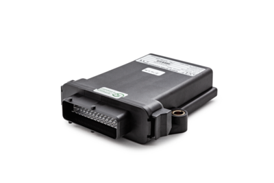
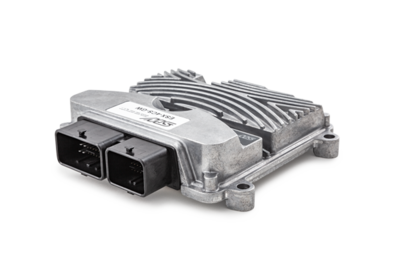
STW ESX 3XM scalable platform
That’s why the 3XM was selected for this project. The ESX-3XM is a highly adaptable, scalable, powerful controller with 23 configurable I/O up to 65 I/O. It can be considered the little brother of the older ESX-3XL, with the same power and memory, but half the I/O and half the size. The base version, with 23 inputs and outputs, provides 4 CAN interfaces and 1 RS232 serial interface. 8 low side outputs were added in this project with an expansion board in all ECUS and two additional CAN interfaces on another expansion board were added for the master ECUs.
The processor system of the ESX-3XM, based on the powerful TriCore TC1796 from Infineon, is clocked at 150 MHz and is backed by 4 MB of RAM and 6 MB of Flash. A buzzer for audio alarms, and system and user LEDs for diagnostics help basic troubleshooting of the system without the need for any special software tools.
The ESX-3XM is freely programmable in CODESYS (version 3.x), in the ‘C’ Language or with a Matlab/Simulink support package. All of the inputs, outputs and communications port are fully accessible and configurable through extensive BIOS libraries. Multitasking is possible and necessary in this project
The ESX-3XM is designed for safety-related applications according to SIL2/ISO 61508. Safety functions are available in the C programming language and in CODESYS by the beginning of 2015.
STW ESX CAN Unimissio protocol
As explained before the CANopen Safety protocol (with frame redundancy) was not selected in this distributed architecture for the communication between all steering ECUs (master and slaves) in order to maintain a correct bus load and thus ensure a good determinism in the safety frames communication. A TÜV certified proprietary protocol from STW, called ECUS (for ESX CAN Unimissio Safety) was preferred with two big advantages in the project context. Firstly one CAN transceiver only is used. Secondly the safety data redundancy is made inside the frame (for safety data smaller than 4 bytes).
Result: Soon on your taxiway
Performance, safety and reliability requirements could be fulfilled thanks to the common work with STW .
The two models of TaxiBot – one for single-aisle aircraft under final certification tests, and one for wide-bodies – are suitable for all Airbus and Boeing aircraft with no or very minor modification. A major advantage is that TaxiBot, being a completely separate vehicle, does not bring extra weight to the airplane and no reduction in the cargo bay space. There are no motors or equipment to install on-board that add weight and increase fuel burn during flights. In terms of speed, TaxiBot is able to tow an aircraft at maximum take-off weight at 23 knots, equal to the normal taxiing speed.
Lufthansa Technik’s subsidiary LEOS has been testing the Narrow Body TaxiBot since June 2013 at Frankfurt International Airport at night. All No Technical Objection (NTO) tests and the certification tests on the B-737 and A-320 have been performed. Lufthansa Pilots’ reports were very positive during their first runs with the TaxiBot in Frankfurt .The final certification for use with these aircraft is expected before the end of 2014.
The Wide Body TaxiBot prototype dedicated for wide body aircraft, including the A380, is nearing its completion. This machine is the most powerful piece of equipment ever built for a GSE application with more than 1500hp and it will tow a fully loaded A380 (570 tons) at up to 20 knots! With a 12.9 m length, 4.5m width and 50 ton weight, the Wide Body TaxiBot is a unique machine.
Conclusion
The main lesson from this big TaxiBot project, is that breakthrough innovation is still possible in the mobile machinery business, despite (or thanks to) high functional safety constraints but can only be successful in a team including manufacturers, suppliers and end-users.
At TaxiBot project level, four complementary partners (IAI,Airbus,TLD,LEOS) worked together to take this technology from concept to reality. At their sub-system level, DINTEC and STW could also benefit from their long-term relationship to meet the requirements of the vehicle manufacturer. The application know-how of DINTEC in electro-hydraulic and electrical functions for vehicles or working tools, combined with the quality of the STW hardware and core software components, once again achieved OEM satisfaction.