
MAKING MOBILE
MACHINES PERFORM.
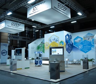
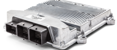
As an international company with its headquarters in Kaufbeuren, Germany, we have been providing high-quality solutions for digitalisation and automation of mobile machinery for over 40 years. We support our customers on their way to making their machines the best in the world with the most innovative technology, with a modular system of generic and customer-specific products, systems and software solutions.
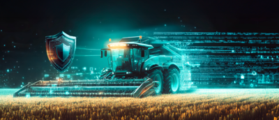
Compatible products and systems from our global partner network complement our STW modular system. We support our customers throughout the engineering and integration process. Our hardware and extensive software toolchain help medium-sized companies and large OEMs improve the performance and efficiency of their machines in a user-friendly way. We enhance safety and prepare our customers to meet future engineering challenges. Our connectivity solutions enable machine-to-X communication, providing networking with cloud platforms and integration of mobile machine operations directly into business processes.
We value and support our employees, and we take our responsibility towards the environment and society seriously. Together with our customers and partners, we are actively involved in important future topics, including the Internet of Things (IoT), Industry 4.0, semi- and fully autonomous operations, and e-mobility.


CASE STUDIES
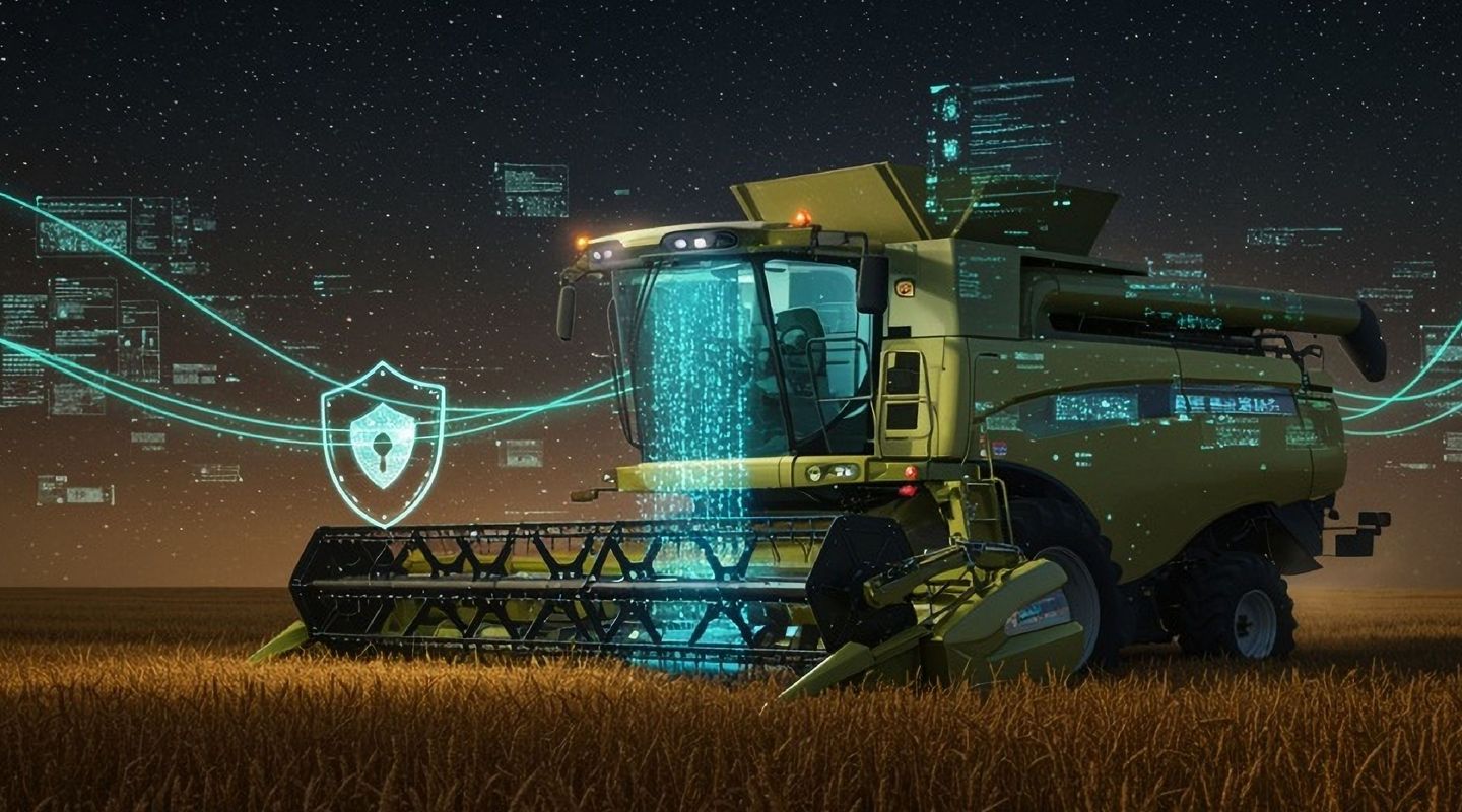
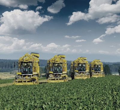
While we are proud of our products and solutions, it is through our customers’ applications that the power in the innovative technology is unleashed. Whether fully networked, highly automated, or operating fully autonomously, an effective mobile machine represents first class interdisciplinary engineering. Robust and safe integration into the system architecture of the machine and its work processes, while remaining convenient and user friendly, is the main focus. With thanks to our customers, here we would like to present a small selection of example applications.
![[Translate to English:] Goldhofer](/fileadmin/_processed_/7/9/csm_2016_Moving_airplanes_safely_Goldhofer_80562b31f3.jpg "GOLDHOFER")


![[Translate to English:] Bauer](/fileadmin/_processed_/4/3/csm_2015_Bauer_Telematik_revolutioniert_den_Markt__c4ac8863f0.jpg "BAUER")
![[Translate to English:] Framo](/fileadmin/_processed_/1/5/csm_2017_eLKW_FRAMO_a02216030f.jpg "FRAMO")


![[Translate to English:] MAFI-TREPEL](/fileadmin/_processed_/7/6/csm_2017_MAFI-TREPEL_Ground_Support_Equipment_064fd4a058.jpg "MAFI TREPEL")
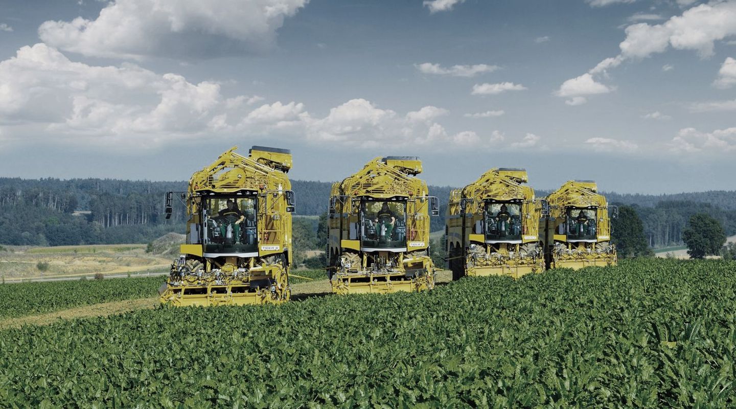
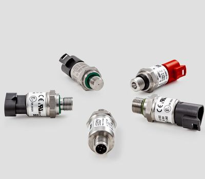
![[Translate to English:] Fendt](/fileadmin/_processed_/2/0/csm_2017_Druckmessung_aus_dem_Baukasten_Fendt_f023655ea4.jpg "AGCO FENDT")


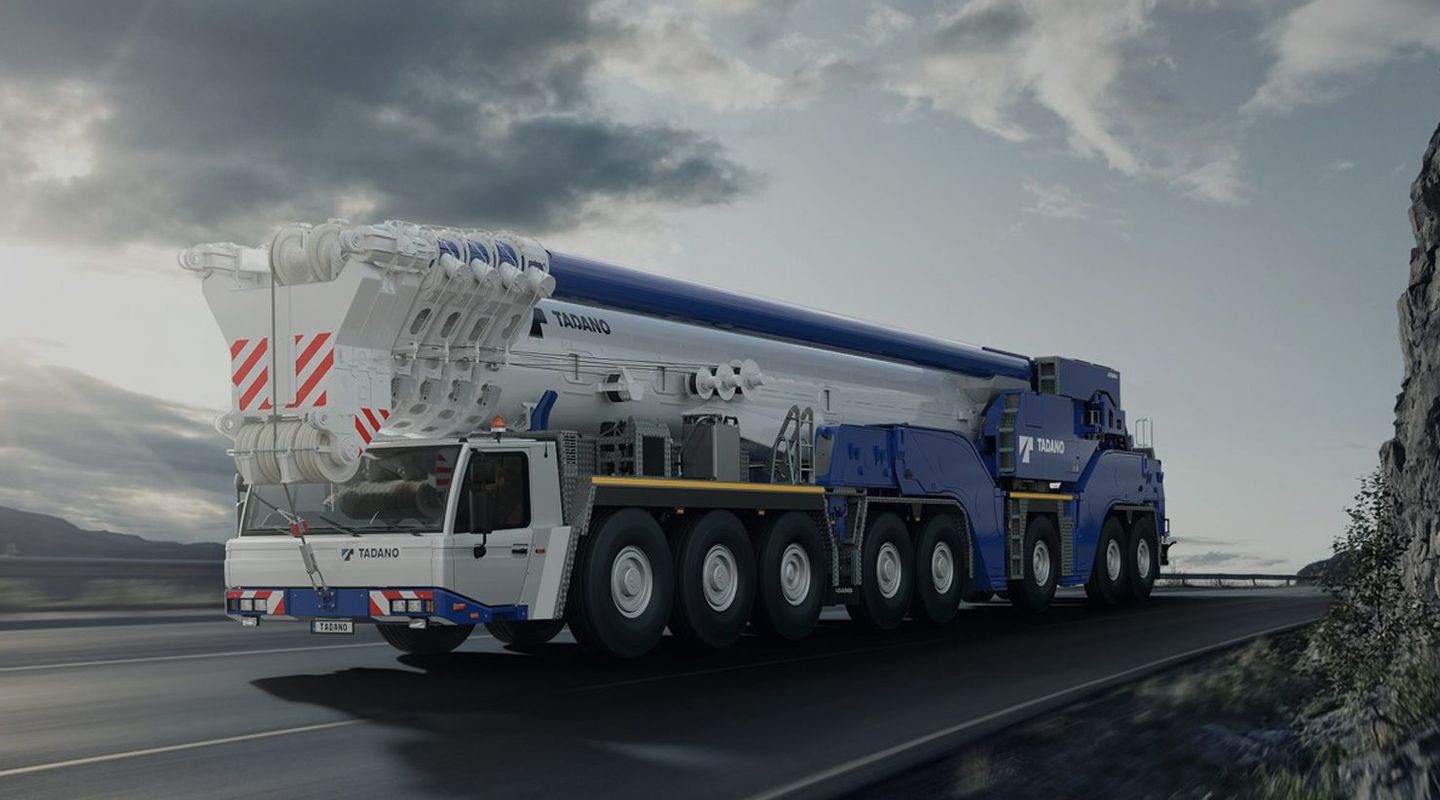
![[Translate to English:] Tadano](/fileadmin/_processed_/c/5/csm_2017_Tadano_All-Terrain_Krane_f7cc8ea7c4.jpg "TADANO")
![[Translate to English:] Fendt](/fileadmin/_processed_/6/f/csm_2016_Energie_im_Traktor-Intelligent_verteilt_fe620ae028.jpg "AGCO FENDT")


![[Translate to English:] Pepper Motion](/fileadmin/_processed_/4/b/csm_pepper_sono_motors_04_102db6310f.jpg "PEPPER MOTION")

![[Translate to English:] Bauer](/fileadmin/_processed_/1/d/csm_2017_Bauer_Anbindung_an_Maschine_f3f7b3a62e.png "BAUER")